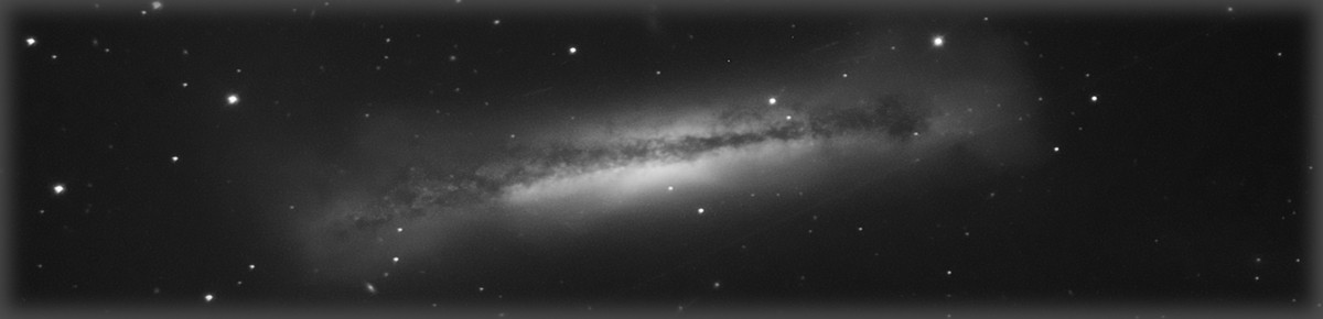

Starting in the spring with the acquisition of my AT8RC, I was worried about whether my my past polar alignment and tracking have been adequate to support this new, much longer focal length. I got hung up on polar alignment accuracy, initially, but after starting to image, it appears that either my PE is too bad to guide out. This picture of the Eagle Nebula (12 minute subs, lightly processed to see what is happening) shows the trailing of concern. To my eye, the main issue with the image is the overall star elongation, more or less oriented in the same direction over the entire image. I would expect that errors caused by polar alignment would show up more as rotational problems than this type of consistent streaking. Note: As always, click on the image three times to see the full size image. First click goes to image gallery, second click expands to full size of browser window, and third to full size of image.
So after some thinking, some forum searches, and some fruitless imaging nights, I decided to try to analyze my periodic error and attempt to logically determine the source of my difficulties.
To undertake the Periodic Error measurement, I decided to use CCD-Ware’s tool, PemPro. It includes modules to assist in both polar alignment and periodic error measurement. All of the measurements were taken through the AT8RC with a Meade DSI camera, resulting in an image scale of around 1.2 arc-sec/pixel. The load was not necessarily consistent. In some cases, the load included a guide scope and camera to simulate my fullest load, in others, it only included the 8″ AT8RC.
The first set of data shows the state of the mount before any work was done.


Great huh? That is what I thought at the time. But I came to understand, perhaps, a little about this data and what it means. The initial chart simply shows the periodic error as measured by the distance the mount travels away from its expected position. The seven cycles are adjusted for any drift caused by less than ideal polar alignment. This data is captured by taking images of a star while the mount is tracking (but not guided) and charting how the star moves compared to it’s expected position.
It can be difficult to understand exactly what the data is telling you in the initial form, and that is where the second chart comes in. The second chart is a frequency analysis, which essentially breaks down the overall error into errors that are contributed by individual frequencies. The fundamental frequency for my mount is just under 8 minutes (which equates to one revolution of the worm gear). Other periods of interest are also noted in the graph.
Finally, the third chart displays two curves. The first is a fitted curve to the periodic error data measured in the first chart as can best be fitted when combining all the cycles (that is, what do you get when you combine all those cycles into one curve). The second curve is a calculated curve that reflects the best effort to correct, by “programming out”, the periodic error with Periodic Error Correction. The idea behind periodic error correction is to modify the standard tracking of the mount by anticipating repeatable errors and sending guiding commands to the mount before those errors occur. Inherently, this periodic error correction is limited to errors that are integer multiples of the worm period.
So Ray Gralek, the author of PemPro, was nice enough to take a look at my data and offer an opinion. In his view, the contribution of error by the stepper motor gear is rather high. And unfortunately, because the stepper motor gear period is not an even integer multiple of the worm period, there is not an opportunity to address this error with Periodic Error Correction (PEC). So the only real way to address this error is to look into any correctable mechanical causes.
As I was deciding what to do next, I did happen to notice that there was a discernible “clunk” in my mount in Right Ascension, and I began to wonder, hopefully, whether this might actually be the cause of my stepper motor gear error. There are articles on line describing methods for adjusting the mesh, and especially there is one I liked in the files section of the EQ6 Yahoo Group. I followed these instructions and combined with an overall adjustment to the tightness of both the RA and DEC axes, I headed out with renewed confidence to take some beautifully tracked pictures.
Not so fast, astronomy breath…
Another round of attempted image capture (no PEC applied), another set of images that may or may not have been any better. SO… I took another round of data, showing the mount after the mesh adjustment. Note this data was taken with a fully loaded mount.


So now for some interpretation… To me, qualitatively, the data may have calmed down a little bit, but while it is a relatively smaller magnitude, there is still a relatively large contribution from the stepper motor gear. Further, the rather large data spikes are still evident in the raw data. Perhaps these represent excursions that are just too large and rapid to be able to adequately guide out.
So, I was sure that if I took the mount apart, I would almost certainly find something that was lodged in a stepper tooth and if it were cleaned out, thinks would be miraculously improved.
And so, it seemed to me, while already taking the mount apart, it would make sense to also perform a “hypertune”… the primary components of this are a general cleaning and adjusting and also the replacement of the questionable quality bearings which support the worm gears. So I ordered a kit, and performed the hypertune.
This time, since the moon was living large, I went and captured more PE data rather than directly trying to image. The results of the post-hypertune analysis follow:


Hmmmm. So qualitatively, I might try to talk myself into thinking that the data is perhaps a bit smoother, and that the non-worm period errors are perhaps tamped down a bit… but overall, the PE is still about the same. NOT the home run I was looking for. The pessimistic side of me wonders if I have made much of a dent in the problem, or have even helped to make the errors more guide-able. I am hoping, but not convinced.
For completeness, to date, here are a few cycles of data (it was getting late) with PEC applied:


Conclusion
So what does this all mean? Well, I am not yet sure. I can’t help but feel like I haven’t really addressed the issue. Granted, there is still substantial periodic error contribution from the worm gear, but if it is repeatable, it can be removed with correction. Based on an article I found, I have placed an order for replacement stepper gears (and transfer gears, too). Based on that data point of ONE, i hope that the stainless stepper gears are higher quality and of a better tolerance. Anyhow, they are not very expensive, so it seems worth a try. Beyond that, I am considering whether I should just stick with the shorter focal length scopes and this particular mount.
Regardless of how this phase turns out, it has presented a vehicle to much better understand my mount, Periodic Error, and PHD Guiding. The images I have taken with a shorter focal length scope while busy trying to sort out these tracking issues show tighter stars and improved tracking over images I have been able to capture in the past.