Processing Potential

In terms of astrophotography, I am still much closer to a stumbling, bumbling amateur than to seasoned veteran.  This, is hardly a deterrent to spouting half-baked opinions freely, as both of my readers have likely noticed already.

As an avid woodturner/woodworker, I can attest to a common thread between woodworking and astrophotography… that the first, and often most enticing solution to any problem is to….  wait for it…. buy some gear!  Specifically in woodworking, where I am more proficient than with astrophotography, I have come to realize that this “ready-shoot-aim” approach is fun, but not necessarily productive.  In fact, as my woodworking skill level improved, I noticed the piles of unused and irrelevant tools grows… as the quality of work improves.  Hmmm.  That is not to say that there isn’t a place for new and better gear, it is just that now I am more likely to wait to buy a new accessory for my table saw until after the second time I really need it, instead of getting it because “I bet I can use that some day”!!!

Since the toys/accessories for astrophotography are rather expensive, and since (no disrespect to my woodworking friends) the complexities and variability are even greater, I am trying to apply the lessons learned in woodworking to astrophotography.  Which finally brings me to the point of this article…  skill-building.  There is no substitute.


m33_first-processing-try
M33 Processing Example as of September 2010

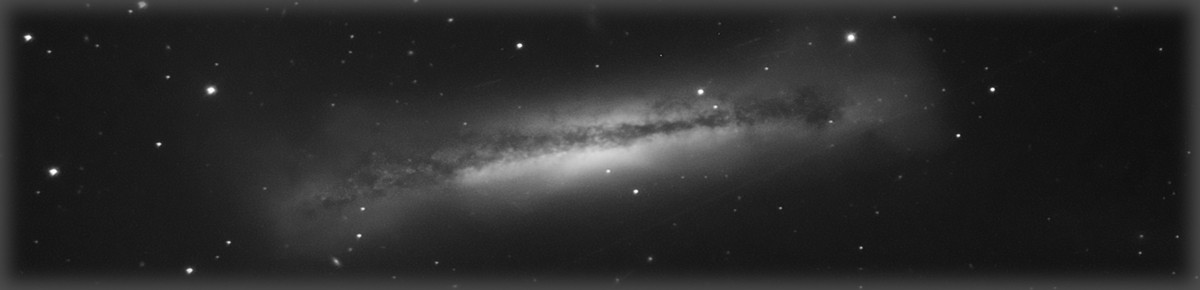
Late last summer, at the Almost Heaven Star Party, I gathered nearly 4 hours of data on M33.  A rather bright target, under dark skies, and pretty well tracked.  I got home and excitedly processed this data and I was really happy with it.  At that time almost all of my processing knowledge was based on the excellent DVD book by Jerry Lodriguss, “Catching the Light“.  I was slightly troubled by the fact that the image wasn’t NASA calendar ready, but still, it was the first full year of trying astrophotography… what’s not to like?

As the fall faded into winter and a frigid temperatures curtailed any NEW image collection, I revisited a few of the more successful targets from over the summer (ok the one!).  After reading and searching, one can find almost endless sources of guides, tutorials, and instruction on using Photoshop.  I settled in on two that are focused on astrophotography and were very helpful to me.  First, Warren Keller’s IP4AP (Image Processing for Astrophotographers) series are short, scripted segments averaging around 5 minutes in length.  They are snappy and full of information.  Additionally, a number of processing articles by Warren  are published in Astrophoto Insight, the digital magazine about astrophotography.  Contrasted with these tutorials were the somewhat more lengthy and detailed style of Adam Block from his series “Making Every Pixel Count“.  Adam, is a slightly more subtle processor than some (my viewpoint) but takes amazing photographs and shares techniques that I have found to work extremely well for me. He also takes you through examples from beginning to end.


m33_12_15_finished
M33 Processing Example as of December 2010

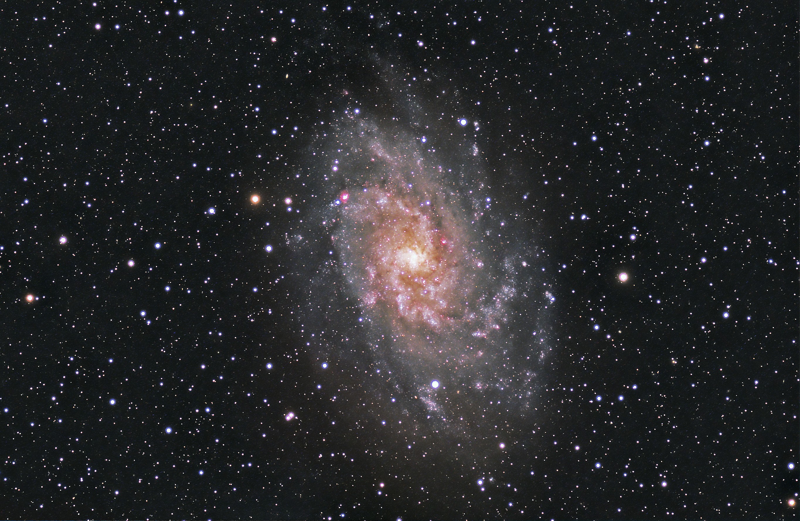
So in early December, armed with my freshly acquired video knowledge, I went back and reprocessed M33.  And then I reprocessed it again.  And again.  And finally, I thought I had an amazing photograph that would surely make all of my friend’s years complete, if only they had their own copy… say as a Christmas present!  Well, I probably didn’t really make anybody’s year, but everyone did seem to appreciate the photos.

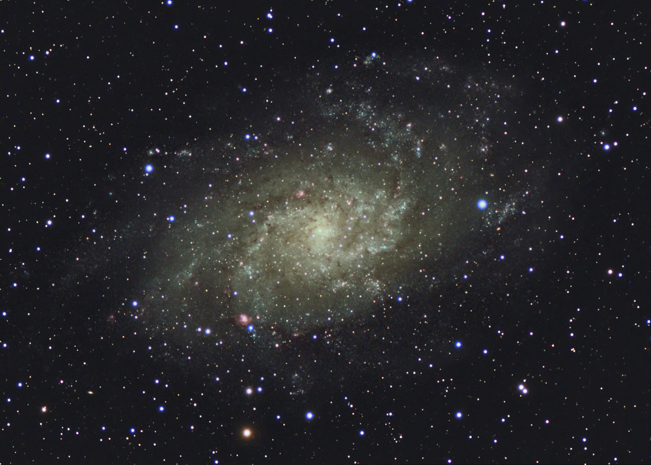
But I was still unconvinced that I was getting everything that I could from hours of data in wonderfully dark skies on a relatively easy and bright object.   So I kept reprocessing, then reviewing tutorials, then reprocessing some more and reviewing some more.  I also re-did calibration frames retook grey cards for white balancing, and even went to sleep watching video tutorials (note whenever my wife looks at me and rolls her eyes about this, I always smile and remind her that she could have married a guy who spends every night in a bar!).


m33__redone_again
M33 Processing Example as of August 2011

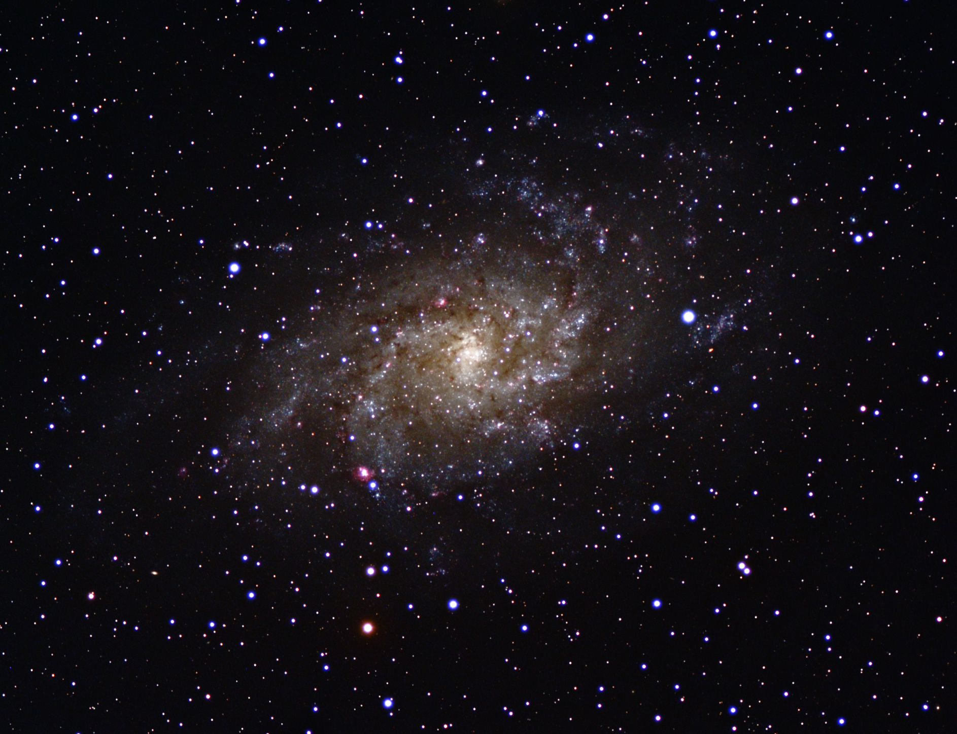
So at the risk of disappointing everyone who was on my Christmas gift list last year, here is where I am today… I want to emphasize again, that each version of this target is the exact same data.  The only difference is in the operator understanding better what to do with it.  I only hope that the improvements will continue to come.  I am still interested in learning and applying deconvolution techniques and perhaps some DDP as well.

There is always room for improvement that doesn’t cost an arm and a leg.  Now if you will excuse me, I have to go check on something on Astromart.


Since my last update, over two years ago, I would like to think I have added to my processing skills.  The data from this capture is old enough that it was taken with my Canon Rebel XT, and apparently the fits headers it created don’t agree with CCDStack2.  However, I still decided to take a calibrated (such as I was doing at the time), combined frame and try a little more enhancement with CS4.  The differences are subtle, I think, but nonetheless, an improvement.  Certainly, the fainter structures are more visible.
M33_2013_Version
M33 – Processed October 2014

More Periodic Error?

M16 - Differential Flexure Reduction Attempt
M16 – Differential Flexure Reduction Attempt

After sharing my last entry with the mailing list for our local club, several members were kind enough to take a look at the write up I provided.  Consensus among those members was that I am not so much looking at a tracking problem as I am a differential flexure problem between the guide scope and the main scope.  They suggested that the pattern of the trailing pixels across the frame, largely in a consistent direction, couldn’t really be explained by tracking problems or polar alignment issues, but rather by a slight but steady flexing problem.  The wisdom on this, both from club members and from other reading on the interweb, is that “It Doesn’t Take Much!”.

It is not to say that periodic error and mount performance might not be a contributor to my elongated stars.  Obviously, periodic error (and especially non-periodic error) improvements are sure to at least make tracking easier and more accurate.  But the hypothesis that was suggested, is that poor tracking would not explain the hot pixel pattern shown in the image of my last post.One straightforward solution to reducing differential flexure is to use an off axis guider.  In short, this device uses a small prism mirror to pick off a small portion of the incoming light through the main scope, rather than using a guide scope.  While this setup can me a bit more difficult to get set up than a separate guiding scope, it inherently removes potential flexure between the two scopes and the connecting mounting hardware.  This is especially recommended on larger scopes and scopes where the mirrors are not firmly attached, and so, can shift as the mount moves to differing orientations.  I found a used one and will give it a try once I have the correct combination of spacers to use.In the meantime, though, I decided to try an experiment with what I had on hand.  Rather than use my ED80 on by ADM side-by-side setup, I setup my 102mm imaging refractor directly on the top rail of my AT8RC.  I wasn’t sure, but wanted to see if this arrangement was more rigid.  Also my 102 has a more rigid focuser, and the AT8RC sits directly on top of the mount  rather than slightly off-set.  I really haven’t heard of anyone having issues with the rigidity of the ADM side-by-side setup, but I decided to try this arrangement, anyhow.The image above is the result of that effort.  The tracking isn’t perfect, but the trailing hot pixels are much more tightly grouped together.  The image itself is hazy and soft because of the conditions, but the star shape is improved somewhat.  Note that the image duration for the subs in this image are the same as the subs in the image from my last post (12 minutes).  I am encouraged that with an off-axis guider, results will be even better.  And further, I located a higher quality stepper motor gear to replace the existing gear,  This represents the last identified anomaly from the periodic error investigation and resultant tune-up that I performed.Note that the conditions were terrible the night I ran this experiment.  I couldn’t spot Polaris until after 10PM though the haze and clouds.  It was so humid that condensation formed on the glass of my cooled CCD, and after it dried, it left behind a number of spots.  Barely any of the stars of Sagittarius were visible.So a tip of the hat to folks at AAAP, especially Nate, Fred, and Frank, who took and look and helped me out.

Periodic Error Analysis

m16-tracking problem

Starting in the spring with the acquisition of my AT8RC, I was worried about whether my my past polar alignment and tracking have been adequate to support this new, much longer focal length.  I got hung up on polar alignment accuracy, initially, but after starting to image, it appears that either my PE is too bad to guide out.  This picture of the Eagle Nebula (12 minute subs, lightly processed to see what is happening) shows the trailing of concern.  To my eye, the main issue with the image is the overall star elongation, more or less oriented in the same direction over the entire image.  I would expect that errors caused by polar alignment would show up more as rotational problems than this type of consistent streaking. Note: As always, click on the image three times to see the full size image. First click goes to image gallery, second click expands to full size of browser window, and third to full size of image.

So after some thinking, some forum searches, and some fruitless imaging nights, I decided to try to analyze my periodic error and attempt to logically determine the source of my difficulties.

To undertake the Periodic Error measurement, I decided to use CCD-Ware’s tool, PemPro.  It includes modules to assist in both polar alignment and periodic error measurement.   All of the measurements were taken through the AT8RC with a Meade DSI camera, resulting in an image scale of around 1.2 arc-sec/pixel.  The load was not necessarily consistent.  In some cases, the load included a guide scope and camera to simulate my fullest load, in others, it only included the 8″ AT8RC.

The first set of data shows the state of the mount before any work was done.

Initial Assessment
Initial Assessment
Spectrum for Initial Assessment
PE Curve from Initial Assessment

Great huh? That is what I thought at the time. But I came to understand, perhaps, a little about this data and what it means. The initial chart simply shows the periodic error as measured by the distance the mount travels away from its expected position. The seven cycles are adjusted for any drift caused by less than ideal polar alignment. This data is captured by taking images of a star while the mount is tracking (but not guided) and charting how the star moves compared to it’s expected position.

It can be difficult to understand exactly what the data is telling you in the initial form, and that is where the second chart comes in. The second chart is a frequency analysis, which essentially breaks down the overall error into errors that are contributed by individual frequencies. The fundamental frequency for my mount is just under 8 minutes (which equates to one revolution of the worm gear). Other periods of interest are also noted in the graph.

Finally, the third chart displays two curves. The first is a fitted curve to the periodic error data measured in the first chart as can best be fitted when combining all the cycles (that is, what do you get when you combine all those cycles into one curve). The second curve is a calculated curve that reflects the best effort to correct, by “programming out”, the periodic error with Periodic Error Correction. The idea behind periodic error correction is to modify the standard tracking of the mount by anticipating repeatable errors and sending guiding commands to the mount before those errors occur. Inherently, this periodic error correction is limited to errors that are integer multiples of the worm period.

So Ray Gralek, the author of PemPro, was nice enough to take a look at my data and offer an opinion. In his view, the contribution of error by the stepper motor gear is rather high. And unfortunately, because the stepper motor gear period is not an even integer multiple of the worm period, there is not an opportunity to address this error with Periodic Error Correction (PEC). So the only real way to address this error is to look into any correctable mechanical causes.

As I was deciding what to do next, I did happen to notice that there was a discernible “clunk” in my mount in Right Ascension, and I began to wonder, hopefully, whether this might actually be the cause of my stepper motor gear error. There are articles on line describing methods for adjusting the mesh, and especially there is one I liked in the files section of the EQ6 Yahoo Group. I followed these instructions and combined with an overall adjustment to the tightness of both the RA and DEC axes, I headed out with renewed confidence to take some beautifully tracked pictures.

Not so fast, astronomy breath…

Another round of attempted image capture (no PEC applied), another set of images that may or may not have been any better. SO… I took another round of data, showing the mount after the mesh adjustment. Note this data was taken with a fully loaded mount.

Assessment after Mesh Adjustment
Spectrum After Mesh Adjustment
PE Curve After Mesh Adjustment

So now for some interpretation… To me, qualitatively, the data may have calmed down a little bit, but while it is a relatively smaller magnitude, there is still a relatively large contribution from the stepper motor gear. Further, the rather large data spikes are still evident in the raw data. Perhaps these represent excursions that are just too large and rapid to be able to adequately guide out.

So, I was sure that if I took the mount apart, I would almost certainly find something that was lodged in a stepper tooth and if it were cleaned out, thinks would be miraculously improved.

And so, it seemed to me, while already taking the mount apart, it would make sense to also perform a “hypertune”… the primary components of this are a general cleaning and adjusting and also the replacement of the questionable quality bearings which support the worm gears. So I ordered a kit, and performed the hypertune.

This time, since the moon was living large, I went and captured more PE data rather than directly trying to image. The results of the post-hypertune analysis follow:

Assessment After Hypertune
Spectrum After Hypertune
PE Curve After Hypertune

Hmmmm.  So qualitatively, I might try to talk myself into thinking that the data is perhaps a bit smoother, and that the non-worm period errors are perhaps tamped down a bit… but overall, the PE is still about the same.  NOT the home run I was looking for. The pessimistic side of me wonders if I have made much of a dent in the problem, or have even helped to make the errors more guide-able.  I am hoping, but not convinced.

For completeness, to date, here are a few cycles of data (it was getting late) with PEC applied:

Assessment After Hypertune PEC Applied
Spectrum After Hypertune PEC Applied
PE Curve After Hypertune PEC Applied

Conclusion

So what does this all mean? Well, I am not yet sure. I can’t help but feel like I haven’t really addressed the issue. Granted, there is still substantial periodic error contribution from the worm gear, but if it is repeatable, it can be removed with correction. Based on an article I found, I have placed an order for replacement stepper gears (and transfer gears, too). Based on that data point of ONE, i hope that the stainless stepper gears are higher quality and of a better tolerance. Anyhow, they are not very expensive, so it seems worth a try. Beyond that, I am considering whether I should just stick with the shorter focal length scopes and this particular mount.

Regardless of how this phase turns out, it has presented a vehicle to much better understand my mount, Periodic Error, and PHD Guiding. The images I have taken with a shorter focal length scope while busy trying to sort out these tracking issues show tighter stars and improved tracking over images I have been able to capture in the past.


Polar Alignment – Part 2

As April is mere hours from becoming May, I am surprised and disappointed that I still haven’t been able to get out for a real night of astronomy.  Setting up this blog was exciting in February and March in anticipation of getting out, but at the end of April, it is the tiniest bit sad…

However, here we go anyway.

On an EQ-G, initial polar alignment of the mount can be achieved through the polar alignment scope and EQMOD’s polar alignment utility.  Through a simple series of steps, EQMOD will end up placing an alignment circle in the appropriate position.  The operator then uses the mount alt and azimuth controls to move Polaris into the small alignment circle, and polar alignment should be achieved to the inherent level of accuracy allowed by this method.  There are some nice pictures of the results in my previous post.  This is the approach I have used prior to this year, but I don’t really know whether it is good enough. 

From reading various yahoo groups, I suspect the majority of contributors would think that polar scope alignment method is not good enough for long exposures, and particularly, not good enough for long exposures at 1625mm focal length.   Additionally, a disadvantage of using the EQMOD utility is that the alignment must be completed without having the gear fully loaded on the mount, or the gear may collide into the tripod/pier.  Further, some suggest that fully loading the mount may induce some differential flexure and affect polar alignment.  Also, this approach means that the gear is always being set up after dark, after Polaris becomes visible in the polar scope.  The budding photographer may, at times, prefer to get set up before dark.

As an alternative to the polar scope alignment method (which is certainly more than adequate for visual observing), there are also software tools available that can make use of the main telescope to assist in polar alignment.  Here is one nice reference on polar alignment software.  For the most part, these polar alignment software tools fall into two main categories.  The first category relies on evaluating the difference between actual star positions and expected star positions to calculate any polar alignment corrections that are needed.  The number of iterations required for an adequate result is based on the accuracy of the initial rough polar alignment.  The second software category is a software-assisted drift alignment – a method that relies on observing the path a star deviates from its expected path over time, then calculating needed alignment corrections.

One software tool, Alignmaster, is a member of the first category.  I have only briefly tried to use this so I have yet to form a solid opinion.  Very first impressions are:

  • The “best” star pairs it wants you to use are often quite low to the horizon and hard to locate
  • It does not attempt to use any installed cameras, so these must be driven by other software (or you could use an illuminated reticule and do it visually)
  • If it works and is accurate, it is likely to be substantially faster than software assisted, drift alignment software
  • Some people in the “groups” say it works great

There are number of examples of the category 2 software, with prices ranging from “free” to $150+.  In several cases the polar alignment function is just one of a suite of programs included in the package.  While my instincts are to purchase the most expensive package first, maybe, for once, I will start instead with a free one.   One example of this program is EQ Align.  Although it sounds like it might be a member of the EQMOD family of software, it is not.   Again, based on no actual experience to date:

  • This software can fully integrate with both the mount and the camera
  • There are comments about earlier versions being buggy, but also those bugs have been resolved and the developers are very responsive
  • The program was developed in Spanish but is largely translated and seems fully usable to a non-Spanish speaker
  • The drift method is generally acknowledged to be the most accurate alignment method, but does take some time, because as the name implies, it depends on tracking how far a star drifts over time

In summary, the initial strategy I plan to follow is to switch my polar alignment method from the use of the polar scope to the use of a software assisted method described above.  Initially, it will be necessary to master the techniques in these methods and become proficient enough to be able to form an opinion as to which method is “good enough”.  Obviously the polar scope can still be used to approximate polar alignment by estimating the position of Polaris through the scope.  But the step of actually rotating the polar scope to align the correct hour-angle actually be done, and a visual approximate will instead need to be employed.

Hopefully, I will be able to report some initial results on these approaches soon… and also to comment on first light on my now  6-week old AT8RC.

Polar Alignment – Part 1

Actual view of laptop screen
Polaris perfectly aligned, right???

For the 2011 season, as I trek into the uncharted territory of capturing images at a focal length of 1625mm at f/8, it can only help to ensure that tracking is as good as it can possibly be.  It is easy to find research material about what works for others (qualified and unqualified), how good tracking must be for given image resolutions and other theoretical goals for producing excellent images.  That research highlights the important considerations for adequate tracking.  At some point, though, the experimenter/engineer in a person takes over and insists that he/she tests and confirms what works… with the proof, ultimately, in the pudding.   My quest for better tracking will initially focus on polar alignment.

Last season and before, my thought was to use the polar alignment scope, get Polaris in the little circle, and polar alignment would be good enough.  And perhaps at focal lengths of 714mm and under, it was acceptable.  But this season, my goals are to both achieve better initial polar alignment, and also assess the quality of alignment once the mount is all loaded up and ready to go.

This entry introduces one tool that may help to improve polar alignment, a neat little trick that was first shared (as far as I know) at  astronomy shed.  This mod is simple and perhaps not really necessary, but it is really cool.  And it can certainly make things easier… which can lead to more accurate results.  In summary, the idea is to attach a web cam to the mount’s polar alignment scope, allowing the polar alignment to be completed in a comfortable, upright, human position, rather than crawling through the wet grass, looking through the polar scope at an awkward angle, and in the case of our club’s Greene County site, kneeling in cow patties!

Installed Webcam
My implementation of the polar cam

Here are additional pictures of my version of the mod, however the whole process is much better demonstrated in a video by Dion from Astronomy Shed.  To date, I have tested this in the front yard to get things focused, and to ensure Polaris will ultimately be bright enough to identified behind the light of the polar scope (and under a glaring street light).  So far, so good.  Looking forward to an actual night out soon.

Next time, more about Polar alignment.